DavidLewis
New member
Hi everyone. Can any of you experts offer me advice about the internal construction of the 3-wire tilt/trim motor I have operating my 1979 Mercury 70HP outboard please? Sorry for the length of this post. I bought the boat for not very much money as an "unknown history, incomplete project", and I'm trying to get everything working without spending much more money...
The tilt/trim system doesn't do anything - it's dead. I'm fine with sorting out the wiring, solenoids, etc., but more fundamentally the tilt/trim motor doesn't run in either direction when connected directly to the battery using jump leads. I have done all the first-stage checks (looking for continuity / shorts between the various windings and metalwork on armature and stator) and as far as I can tell, it all checks out OK. (I don't have a growler though.)

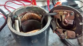
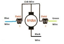
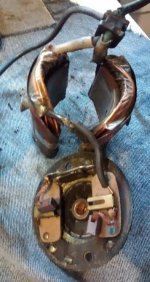
So, I have removed the field windings from the casing and looking at the connections. I don't really believe it's supposed to be like that. It's a three-wire motor. The green wire is attached to one end of the first field winding. The other end of that field winding has a link wire, which runs to the second field winding on the opposite side of the casing. The other end of the second field winding has a blue wire attached. One of the brushes is connected to the link wire that joins the first and second field windings. The other brush is connected to the motor end plate, which has a black wire bolted to it. I've drawn a diagram:


Is that the way it's supposed to be? If so, it means that only one of the field windings (on only one side of the motor!) will be energised when, say, the blue and black wires are connected to the battery. This doesn't seem very likely to me - there surely won't be much of a magnetic field across the armature in this case? The only way of energising both field windings is to connect the blue and the green wires to opposite terminals of the battery, and then the black wire presumably to battery negative. But I've never heard of such an arrangement for a 3-wire tilt/trim motor - it would mean the motor would effectively be a compound excited DC motor. Is that right?
Comments please? Thanks!
David
The tilt/trim system doesn't do anything - it's dead. I'm fine with sorting out the wiring, solenoids, etc., but more fundamentally the tilt/trim motor doesn't run in either direction when connected directly to the battery using jump leads. I have done all the first-stage checks (looking for continuity / shorts between the various windings and metalwork on armature and stator) and as far as I can tell, it all checks out OK. (I don't have a growler though.)

So, I have removed the field windings from the casing and looking at the connections. I don't really believe it's supposed to be like that. It's a three-wire motor. The green wire is attached to one end of the first field winding. The other end of that field winding has a link wire, which runs to the second field winding on the opposite side of the casing. The other end of the second field winding has a blue wire attached. One of the brushes is connected to the link wire that joins the first and second field windings. The other brush is connected to the motor end plate, which has a black wire bolted to it. I've drawn a diagram:


Is that the way it's supposed to be? If so, it means that only one of the field windings (on only one side of the motor!) will be energised when, say, the blue and black wires are connected to the battery. This doesn't seem very likely to me - there surely won't be much of a magnetic field across the armature in this case? The only way of energising both field windings is to connect the blue and the green wires to opposite terminals of the battery, and then the black wire presumably to battery negative. But I've never heard of such an arrangement for a 3-wire tilt/trim motor - it would mean the motor would effectively be a compound excited DC motor. Is that right?
Comments please? Thanks!
David

