Logo

Yamaha Tachometer testing on Alumacraft TP 17.5 2003

Skinny1

Member
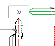
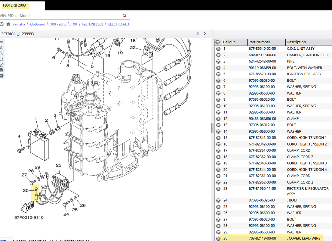
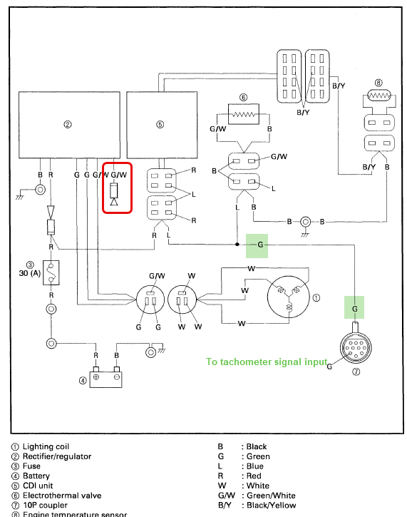
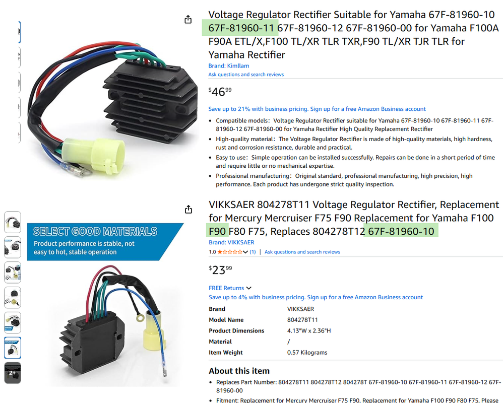
Hello, have an alumacraft TP 17.5 2003 with yamaha 90hp. its a F90TLRB. how do i test the signal wire for the tachometer? use AC voltage? what should it be at roughly 1000 RPM? i put a new tach on it. it showed 1000 RPM for 30 seconds or so and went to zero. I have not been able to get it to do much since. when the motor is started it might go up to 500 and then back to zero. just want to make sure its not a wiring issue before i send it back. Thanks.
 
You can test the green wire for the presence of AC voltage.

The tachometer signal is based on frequency and not voltage. As the frequency changes the RPM will change on the tachometer.

There are a number of connection points on the green wire from the time it leaves the CDI unit to the time that it gets to the tachometer. I would be checking all of those connection points first given the age of the motor.
 
OK, i have 2.54 to 2.59 Volt AC on the signal wire at the dash, at idle - roughly 1000 RPM. the tachometer will set at zero then bump to 4-500 and back to zero, all within 1-2 seconds. Can i test the Hz the same way i test the AC voltage? i am not getting a Hz reading- also not sure i am doing it right. the gauge has a selector 1-12. that has not made a difference on the gauge.
 
If you have a meter that reads Hertz then certainly you can test for frequency.

The fact that the tachometer reading comes and goes leads me to believe there may be an intermittent connection point.

Why not disconnect and reconnect all of the connectors from the motor to the tachometer. Inspect for condition while they are apart. At times the simple act of disconnecting and reconnecting a connector can fix a problem.
 
on a 2003 Yamaha 90 4 stroke, what wire, on the motor can i tap into to test. i can run a jumper directly from there to test. I get AC voltage at the dash but not a Hz signal. i unplugged the 8-10 pin connectors under the dash. they are nice bright shiny brass yet. i dont see any connections in the side gunnel. my manual shows there should be a white wire on the motor. i need to find that.
 
I would start with the dark green wire terminal in the engine harness ten pin connector.

Have you already disconnected and reconnected all of the motor side electrical connectors with no changes being noted?
 
Using a 1995-2004 outboard literature service manual collection F100X. The 3 white wires are coming from the lighting coil. change to green at connection before entering the rectifier. i have disconnected and looked at each connection, all are nice clean shiny. starting to think i have the wrong kind of tach.
 
The tachometer needs to be connected to the "W" terminal on the altenator or a tachometer sender. guessing this will not work on this motor? is there a sending unit i could install on the flywheel?
 
What brand and model of tachometer?

Yes to the question about the tachometer being an analog type.

Yamaha service manual shows the tachometer output as coming from the CDI unit.
 
Does not have a brand. this is what i have.
Specifications:


Name:Tachometer

Material: PVC+Stainless steel+Glass

Panel color:Black

Backlight Color:Red
Fixing dimension: Φ85mm(3-3/8")

Working voltage: 9~32VDC

Working current: ≤100mA

Levels of protection: IP67

Indicating Range: 0~8000RPM

The adjustment range of speed ratio:1-12

Suitable for car truck boats off-roadvehicles boats

This tacho must be hooked up to the "W" terminal on vehicle alternator. Many diesel engines and most inboard gas boat engine alternator have this connection. It can also be working with tachometer sender
 
Take a look at the rectifier/regulator. See if you can find an unused green and white wire. Should have a female bullet connector at the end of that wire. With maybe a plug in the female connector.

Connect that wire to the tachometer input that is stated to be connected to the W terminal on an alternator. See what happens.
 
Here is what i am finding by the rectifier, 3 green wires going in- none with white stripe. took plug apart and rotated to make sure none had white stripe. there is a black ground wire that comes out and a red wire that comes out of rectifier. the only bullet connector wires i see are a yellow wire coming from the harness up above. have a square 4pin not connected that has pink/white and a pink/black wire. and another 4 pin connector that has a black wire and a pink wire.. these 2 connectors would snap together but they are loose. i think i saw in manual that they were for trim gauge which i do not have.
 
What yellow wire? Why did you try that? It has nothing whatsoever to do with the tachometer frequency signal.

Yellow wire is key on battery voltage.
 
Three wires TO the rectifier/regulator. Two are solid green. One is green with a white stripe.

Three wires From the rectifier/regulator. One red, one black, one green with a white stripe.

Should look like this unless someone replaced your rectifier/regulator with a non standard part.

 
Not knowing what tachometer you have, if neither the green wire in the ten pin harness will drive it or a direction connection to the lighting coil and/or the rectifier/regulator will drive it, I would guess the tachometer is not suitable.
 
1759609915108.png
 
this is what i am seeing. 7 is rectifier. 3 green going in and a red and a black coming out. there is not a seperate green white wire. Thank you for you time and effort. i will look for a different analog tach.
 
ok. Rectifier is SH758AA. the pictures i look up show an extra Blue wire that i do not have. would i be better off trying a different rectifier? that might be cheaper than a different tachometer but still dont know if it will work!
 
When i google the Rectifier 67F-81960-11-00 from your schematic the results all have the round connector a black wire and a red wire... the only ones that have the blue wire are for a motorcycle. no idea why... Thank you.
 
Here is something I found interesting. Yamaha built motors for Mercury Marine back in the day. Using the Mercury Marine parts catalog it shows two different rectifier/regulators. One with the third output wire and one without it.

 
Back
Top