Logo

Last seal to be installed in our 1958 Evinrude 35 hp problem...

airrace48

New member
I've been cleaning, re-sealing, & repainting the lower end on our 25936 35 hp. I've never been involved with an outboard motor before although
I have been accused of being a pretty good vintage machinery rebuilder. Through the great service of MarineEngine I've done very well so far.
At times is has seemed mystifying but as with all other non-familiar machinery, "panic" is the first reaction and that goes away gradually with
work and familiarity. I'm proud to say I've made it through the process and have one last dilemma... It's the shift shaft seal. The YouTube videos
have been a great help, along with some phone advice with a super nice guy in Iowa, Dave Stork... The YouTube videos have been wonderful but
there are no videos on the larger/older Evinrudes. These videos are all on 20 hp and lower. Almost all of the principles apply but the shift shaft
seal is an exception. On the lower hp motors the brass bushing and "O" ring are right up on top, easy to see and on which to work. On the 35 hp
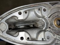
motor the seal seems to be deeply buried in the casting about 7" from both the top and the bottom... Even with a high intensity light I can see
nothing resembling a seal. There appears to be no "brass" way down in there. It does though, look like the same zinc die-cast from which the
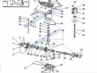
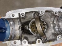
housing is made. I'm attaching a couple of photos but only one seems to allow proper focus. The exploded drawing from MarineEngine indicates
the parts going in from the bottom towards the top, so I would assume that the bushing needs to be driven out from the top to the bottom... correct?
If one looks at the photos I've attached there is not the slightest inkling of a bushing to be driven... The shift rod slides through the "seal location" so
easy that I am quite sure it will not hold water out of the unit. The seal must be replaced and I am mystified as to how to recognize it much less
do it... Any help would be treasured... Steve in Montana [email protected]
 

Attachments

  • IMG_9060 (1).jpg
    IMG_9060 (1).jpg
    57.5 KB · Views: 9
  • IMG_9062 (1).jpg
    IMG_9062 (1).jpg
    72.7 KB · Views: 7
Steve, congrats on getting that far on your first motor. I have not had one of the big old evinrudes apart but I have done a few of the small ones.

One thing stands out to me... if that spot down there looks like the same white die cast metal as the housing, could it actually be the bushing? I wonder if some of the older OMC bushings were white metal instead of brass. The parts drawing description for that item might tell you what it calls out.

On the exploded drawing, if the seal parts stack in from the bottom, then yes I would drive the bushing out from the top. Support the casting on a wood block and use a drift that touches the bushing only. Go easy... that zinc casting will crack before the bushing moves if you hammer hard.

Penetrating oil and patience beats force on those old castings.

Before I buttoned mine up I did a leak test. A couple psi of air in the lower unit with soapy water on the seams and seal areas will show you everything. If the shift rod still feels loose with new seals in, I would just call the MarineEngine parts guys, they have always known the old stuff. Anyone else done a 35 from that era... how did your seal come out. Thanks.
 
Thanks ever so much for the response to my post. I'd like to elaborate a little on my problem. As you have correctly stated, I believe that any bushing should be pressed out from the top. Again, the problem for me is that even with a very strong light there is not the slightest indication
of a circle that would represent the bushing. In other words, sizing a drift would be impossible due to the fact that I have no way of knowing
the outside diameter of a bushing. I think that it is a great idea to give MarineEngine a call. Thanks again... Steve in Montana
 
O-ring 301877
Bushing 394765
Both used until the end of the split gearcase late 70s or so.
Proper tool to drive the bushing out (and yes, it drives down) 304514
Heat the housing a bit to cause it to expand & loosen its grip.

FYI, bushing is approx .765" dia, .580 height & .027" hole.

Enter each part number in Marine Engine search then click on the image for an expanded view.
 
Actually, used on the SPL 28 thru 1996

Correction from above post, the bushing drives ***UP*** to come out according to my late 60 manuals BUT your pictures blurry as they are appear to go down?
Parts book shows the orientation that they drive down to come out.

So exercise caution, clean everything well so it's obvious & wait for Racerone or Timguy to give advise.
 
Last edited:
Wow! Thanks ever so much. Using the part number you provided I was able to find one on eBay for $17 free shipping! Its on the way...
Now, the big question... Referring to the exploded drawing I'm attaching, would you not agree that the bushing, "O" ring and fibre washer
(gasket as MarineEngine.com calls it) would be inserted in that order from the BOTTOM ? I sure could make a nightmare of things if I tried to
do it the wrong way... As explained earlier I can find absolutely no trace from either looking up or down in the casting of the seal. Of course
it has to be there...
Wow! Thanks ever so much. Using the part number you provided I was able to find one on eBay for $17 free shipping! Its on the way...
Now, the big question... Referring to the exploded drawing I'm attaching, would you not agree that the bushing, "O" ring and fibre washer
(gasket as MarineEngine.com calls it) would be inserted in that order from the BOTTOM ? I sure could make a nightmare of things if I tried to
do it the wrong way... As explained earlier I can find absolutely no trace from either looking up or down in the casting of the seal. Of course
it has to be there...
Apparently my .pdf (which is only 860 kb) is not attaching. I'll bet it has to be a .jpg - I will try that now. Bingo...
 

Attachments

  • Exploded .jpg
    Exploded .jpg
    390.5 KB · Views: 3
Call off the dogs!!! Problem solved... I have been able to successfully see the bushing that has been in question. I might have
been lazy. I put a cotton swab on to the end of a rod and used lacquer thinner multiple times along with a tiny Dremel tool brass
brush on an extension to thoroughly clean the area and bingo... there it was in all its "brassy" glory. And many thanks to Droid for
the heads up on the removal tool. I think it is a mis-characterization to call it a "tapered" tool as it is really a "stepped" tool.
Everything is clear now and I appreciate ever so much everyone that has contributed to my dilemma.
 
"Down" to remove, kinda like the exploded drawing shows... Man I cannot thank you enough. Could I lean on you for another question?
I will assume yes. When I get the tool that I bought and replace that last seal I need to pressure test the assembly. This is a basic/stupid
question... To do a test I would like to figure out some simple (bicycle pump???) way of inducing a couple of pounds of pressure to the
lower unit. As long as the shift rod is re-installed I assume the lower unit can be bench tested (not re-attached to the motor). If that is
the case and the skeg is properly attached do I simply soapy water spray the entire casting assembly? It seems to me that if there are
no bubbles, no worries. Am I correct? The only way for (small amount) of pressure to escape would be through the skeg housing or the
propeller shaft seal or the shift rod seal or the little phillips head screw through the housing for the shift "rocker". Thanks as always, Steve in
Montana...
 
It can also leak below the water pump on the vertical driveshaft.

I use a radiator pressure tester which has a built in gauge adapted to a hose barb with the 5/16 course threads & an o-ring.
If it holds pressure, then no need to apply soap solution.

Google Permatex 80019, it is your friend. Use it below.....

Remember the seal must seal statically to the housing & dynamically to the shafts.

Apply this to all outer surfaces of seals & shift shaft bushing prior to driving them in. Also apply to the prop bearing carrier & the mating flange of the gear case.

OMC used to have a product that is NLA but this is essentially the same.

Oh, put a dab on the threads of the bolts that assemble the gear case sections and the water pump housing too. Helps with corrosion.
 
Back
Top