Logo

Mercruiser 120 manifold riser and exhaust don't align

dirkg

New member
Looking for some expert help 'cause I'm a bit lost with the different parts and Frankenstein of a boat project that I got myself into. šŸ‘€

So I bought an old Bayliner with a Mercruiser 120 2.5 as an "economically non viable" project to learn a bunch of things about boats. So far into the project I've done all kinds of cleanup and maintenance just to get the thing in that water, but there's one piece of puzzle that remains lost to me.

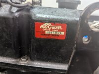
The previous owner fabricated the connection between the manifold elbow and exhaust with a piece of tube that was clearly not OEM, nor the right fit as it was leaking gasses and water. Looking at part diagrams I can't seem to find the right part though, as drawings don't align with my situation.

The elbow (part 55538A2) is not in line with the exhaust (see photos), and needs to make either a S-turn or the elbow needs to be turned 45 degrees. On part diagrams I've found elbows that do so (part 12076A2), but those seem to be for different exhaust manifold - which only have 3 holds instead of the 4 mine has. My engine has the "63122A10" manifold.

Long story short: does anyone have an idea here of what the right solution would be for me? Should I be looking for a different manifold (95862A5) and elbow (12076A2)? Or can I actually re-use my existing manifold and have the most outer waterport be simply blocked (as that's what 12076A2) seems to require? I also looked at the actual drive's exhaust connection and whether there's any differences there, but from what I understand by looking at it there's no alternative as the engine's mount would be in the way of the manifold if you go down straight 🤷

Some pointers here would be extremely appreciated! šŸ™
 

Attachments

  • PXL_20250406_144848483.jpg
    PXL_20250406_144848483.jpg
    971.6 KB · Views: 57
Last edited:
based on your description, what you have isn't going to work...

I'd suggest the transom plate-exhaust pipe drives the 'matching' parts above it. Any idea what was there originally (engine and drive)?

there have been a few exhaust changes over the years and not know what you are working with will just continue the nightmare ...

Thanks @makomark, unfortunately I do not. If it makes things any easier I have the serial numbers. (No photo of the transom plate atm unfortunately).
 

Attachments

  • PXL_20240904_195833738.jpg
    PXL_20240904_195833738.jpg
    904.6 KB · Views: 30
  • PXL_20240904_195836719.jpg
    PXL_20240904_195836719.jpg
    815.7 KB · Views: 34
Parts for SN provided

based on the serial number, the above link should be the original parts...

I'd start with figuring out if you have the Old or New exhaust system and then go from there, back towards the engine, to see what you have and what you should have...
 
I actually did that exercise with some drawings I found of the old en new gen 120 engines. I seem to be having the newer style exhaust system (42421A5), which made me think about having the wrong exhaust manifold.

Looking at the rocker cover, manifold, and other parts, I seem to be having the older style engine, as all of the shift components are mounted on top of it, instead of on the side of the manifold.

There's no info about the history of the engine or the boat available to me, unfortunately.

What I wonder at this point: they might have replaced the engine or stern at some point and got two different generations Frankensteined together? If so, is there any way of working around this that does not require a whole different engine, or drive? Like e.g. swapping the exhaust manifold.
 
So that's where I get confused. The existing exhaust manifold is clearly one from the older series, as it fits this diagram: https://www.marineengine.com/parts/...-manifold-assembly-end-cap-and-elbow-assembly

The lower exhaust assembly is the one marked as "new design", being https://www.marineengine.com/parts/...29718-thru-0b531853/exhaust-system-new-design. Particularly the missing "fourth" water hole is worrying me in this case, as I assume it can't simply be blocked by the newer design elbow(?)

I've been searching endlessly so far for any similar setup like mine so I can find a solution, but seems to be quite exotic. šŸ˜…
 
From what I can see, Based on the serial number on the valve cover, The engine is a "newer" engine then the "older" Intake/Exhaust manifold.

The down tube which bolts to the Transom Is slightly offset (~ 30*-45*) to the right. Is this correct?

What is the issue on 3 holes vs 4 holes you keep referring to? Is this the mounting flange of the down tube and where/how it attaches to the transom?


From what I see at this stage, you have two choices to make this work.

1. The use of a one piece ELBOW which is offset by about 30-45 degrees.
Link- Item 14- https://www.marineengine.com/parts/mercury_marine_parts/sn/0B645170/ 01203007/963_160

2. Or the use of the 2 piece ELBOW assembly Which uses an angled (30-45*) casting as shown in the link

Items 18 & 22- https://www.marineengine.com/parts/mercury_marine_parts/sn/0B645170/ 01203007/963_150


Which ever ELBOW design would appear to work best then all that is needed is a (Heavy duty rubber flexible exhaust tube) that will fit both the ELBOW and down tube. This would be the part that would have for the sake of argument, a 4 inch opening on the ELBOW side and a 3 inch opening on the down tube side.

Depending on which ELBOW works best for your set up is hard to say without physically touching/measuring all the needed parts
 
So that's where I get confused. The existing exhaust manifold is clearly one from the older series, as it fits this diagram: https://www.marineengine.com/parts/...-manifold-assembly-end-cap-and-elbow-assembly

The lower exhaust assembly is the one marked as "new design", being https://www.marineengine.com/parts/...29718-thru-0b531853/exhaust-system-new-design. Particularly the missing "fourth" water hole is worrying me in this case, as I assume it can't simply be blocked by the newer design elbow(?)


I've been searching endlessly so far for any similar setup like mine so I can find a solution, but seems to be quite exotic. šŸ˜…

How are you identifying the Lower down tube as the "newer" design?

What FOURTH WATER HOLE are you speaking to?
 
How are you identifying the Lower down tube as the "newer" design?

What FOURTH WATER HOLE are you speaking to?

I'm referring to the layout of the water openings on the exhaust manifold and elbow. Look at a picture of the current exhaust manifold: https://www.marineengine.com/newparts/part_details.php?pnum=MER63122A13&pass_title=63122A13. There's 4 holes where the (cooling) water is flowing through. When I look at the elbows that have an offset connection, all of them only seem to have 3 holes where the water can go through.

Existing exhaust manifold:
1744019961685.png


One of the offset elbows:
1744019926077.png


Then as for "How are you identifying the Lower down tube as the "newer" design?":
I compared the two part diagrams and the elbow assembly that matches mine is this one: https://www.marineengine.com/newparts/part_details.php?pnum=MER42421A+5. Which is being referred to as newer design from my understanding of the parts diagrams.

From what I can see, Based on the serial number on the valve cover, The engine is a "newer" engine then the "older" Intake/Exhaust manifold.

[...]

So in that case the solution would be to replace the whole manifold with a newer one. Am I correct to understand (browsing around the internet) that those should be direct replacements - as there's also people upgrading their 120's to 140's and swapping manifolds?

If so it sounds like that could be my solution: swap the manifold, use an angled elbow, connect the parts and happy boating.
 
Your down tube as you refer to it as the new design, Does it have the two holes near the top of the tube to the "flappers" that assist in water back flow reduction? The image of the older design down tube doesnt show the holes If I remember correctly...


And to answer you last question, I would agree that updating to a newer design manifold (All in one intake and exhaust) may solve your issue then deciding on which elbow would work best.

As far as the four vs three water passage holes, It appears to me on later (newer) designs they deemed having four water passages not needed. The newer design exhaust manifold only has three passages per parts diagrams. Which reinforces your summary of just upgrading to a newer design exhaust manifold.

It may be that in the prior years before you bought this, the exhaust manifold cracked/failed and they installed the easiest solution to get it running which may have cost them ZERO dollars for an older exhaust/Intake manifold..............
 
Your down tube as you refer to it as the new design, Does it have the two holes near the top of the tube to the "flappers" that assist in water back flow reduction? The image of the older design down tube doesnt show the holes If I remember correctly...

[...]

Correct, it has the two holes for the flappers.

It would have been nice if it was just a simple upgrade of the elbow, skipping the manifold - saving some bucks on that one. Anyway, I'll have a look around to see if I can find anything.

Thanks for the help.
 
I cannot answer if just an Elbow is the answer. But, getting the needed Elbow and rubber boot to connect to down tube, using a three water passage gasket to match may solve your issue without a manifold change. I would try that first and if it doesnt work then look for the exhaust manifold.

Maybe someone else here has had direct experience with miss matched older/newer parts.....
 
Back
Top